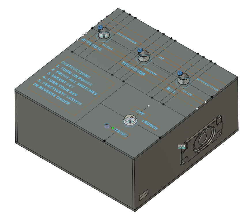
Initial CAD Model

Initial Circuit Test
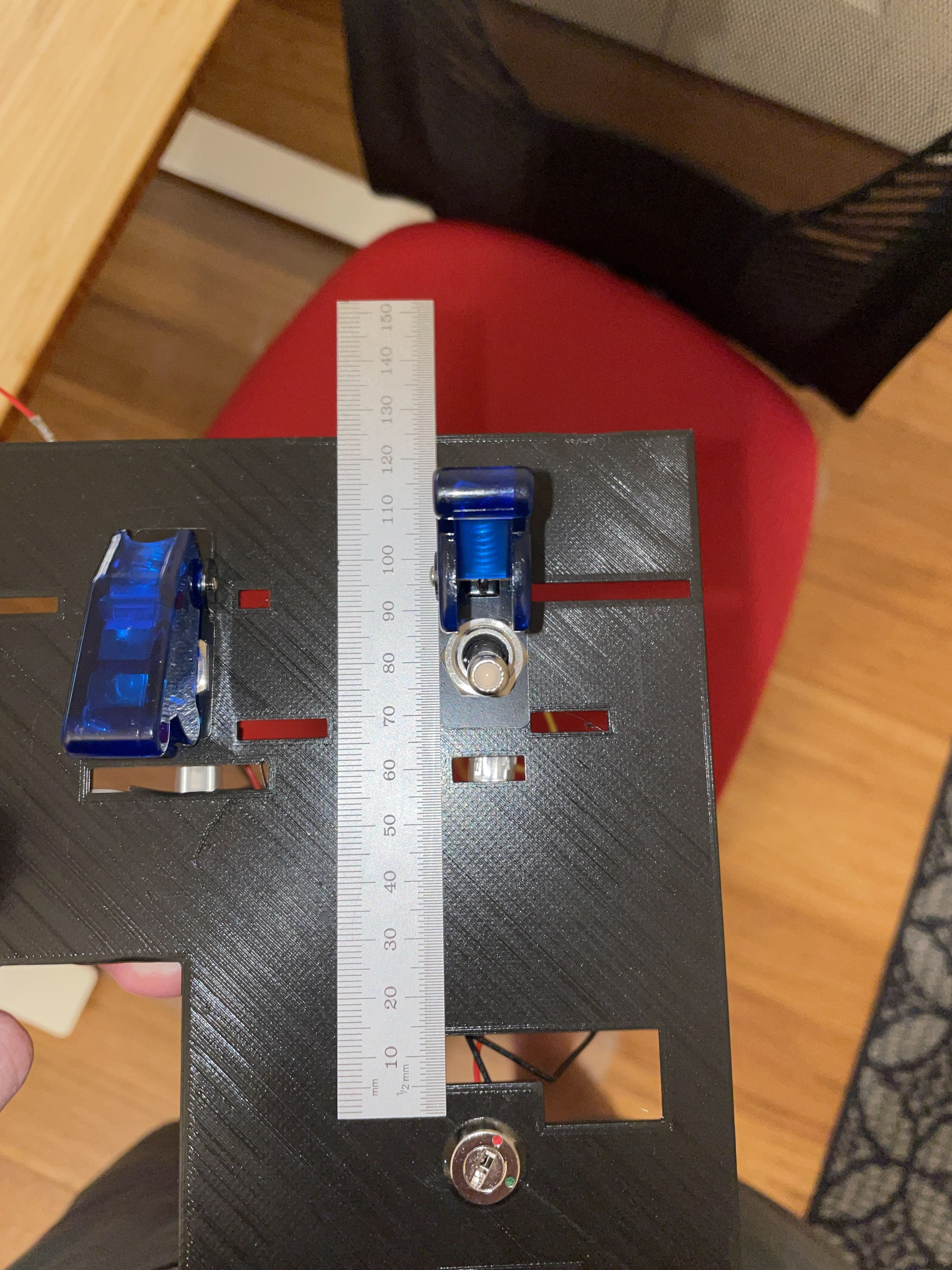
3D Printed Test Plate
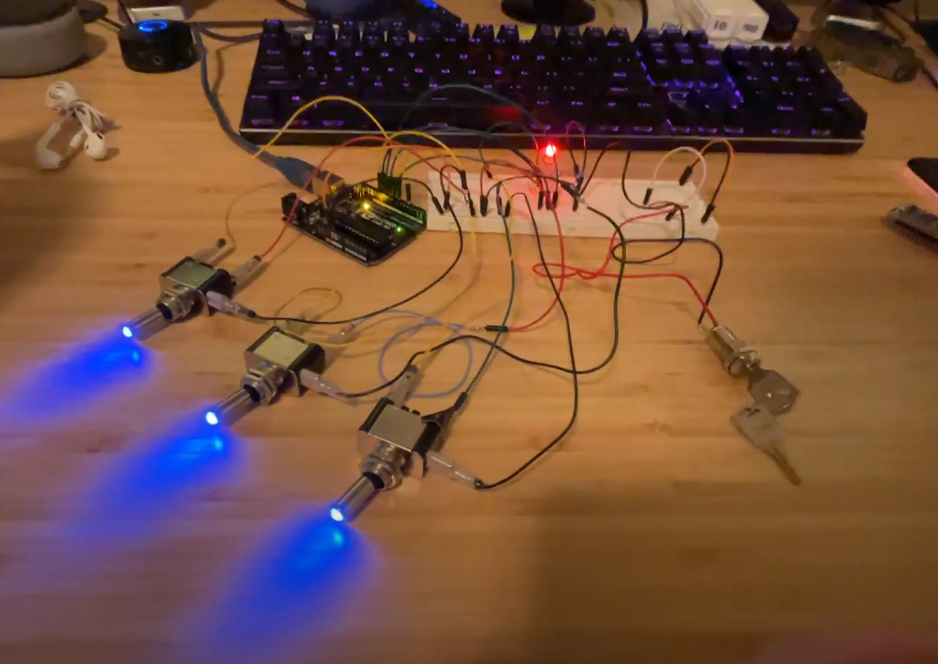
Full Circuit (Sans speaker)
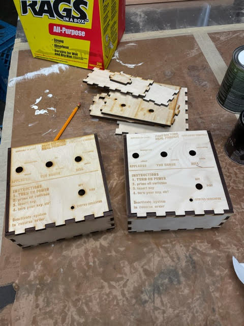
Finished Housings
Received the Boxes, test fit looking good!

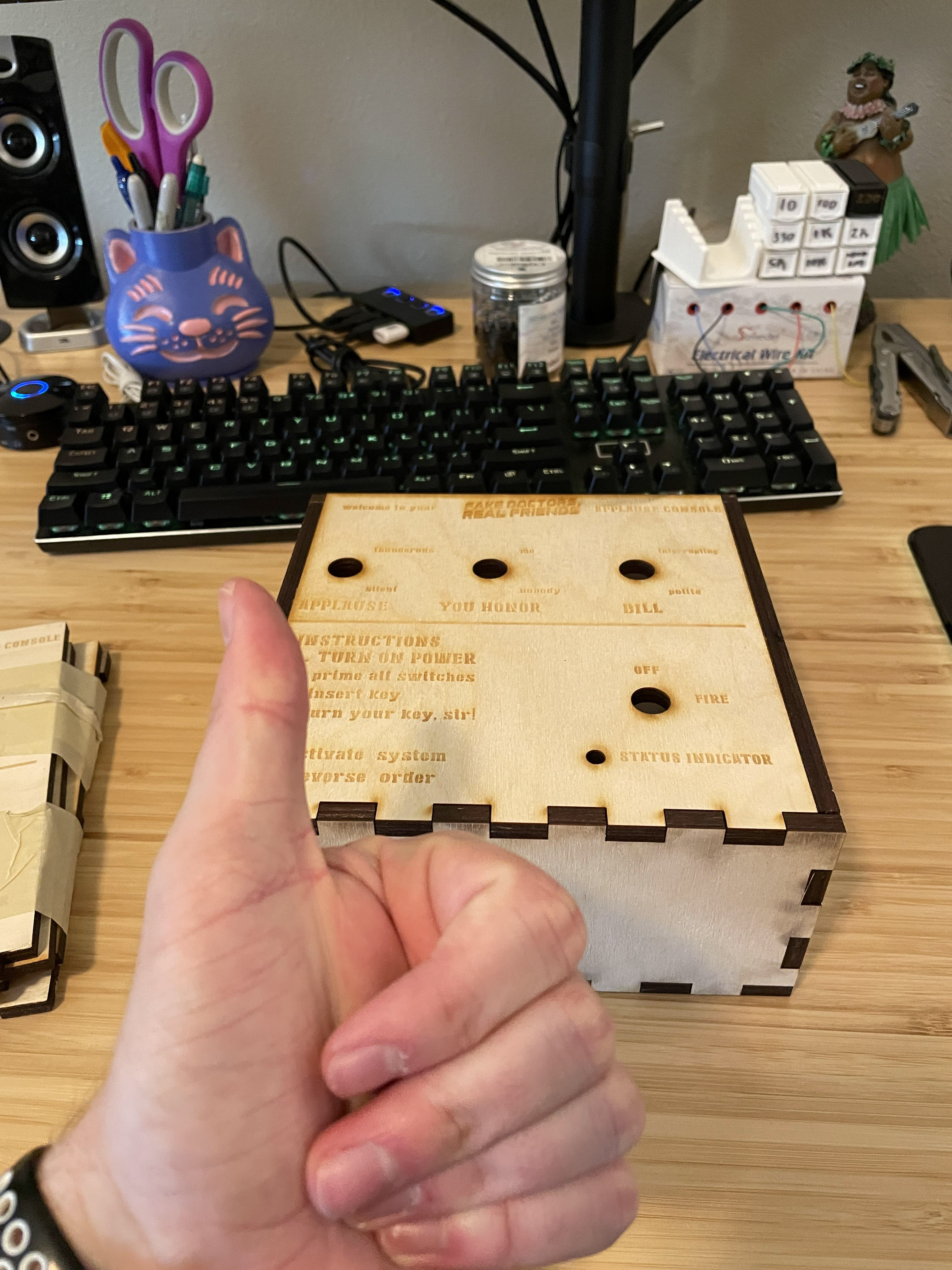
First completed box, power switch and speaker

First completed box in launch mode

First completed box powered off
TURN YOUR KEY, SIR! (PERsonal project, 2021)
This project was born out of a desire to keep moving. In 2021 I began my first real engineering job with ENTEK Manufacturing. While I was off gaining new technical knowledge in this position with each new day, I was left wanting a little more. I spent most of my time on the computer designing or drafting in CAD, so I knew I wanted to actually build something at home. The popular television sitcom Scrubs has been one of my favorite shows since I first watched it as a sophomore in high school. The show ended back in 2009, but in 2020 two of its lead actors, Zach Braff and Donald Faison, started a podcast in which they rewatch the entire series while providing commentary and behind the scenes information. The other half of their podcast team are Joelle Monique and Danl Goodman, their respective producer and sound engineer. When a guest comes onto the show, the two hosts will often call for "thunderous applause" to be played over their guest's arrival. Early on in the podcast's run, Zach and Donald began asking the other to "turn your key" in approval of the applause track being played. The visual presented in this phrase was too strong not to indulge, and I began conceptualizing the "Turn Your Key, Sir" applause launch console right away.
I first began with the electronics involved, as I had experience with basic Arduino-centric projects but nothing that required this many components. I began by simulating the circuit and code online, then testing on the board I had at home. Once I got the circuit to work with some simple LED's and slide switches I had laying around, I sourced my satisfyingly-clicky toggle switches, speaker, amplifier, sound board, and keyswitch. After using 3D printed test boards to make sure my mounting holes were correctly sized for the components, I had two wooden housings laser-cut out of oak wood. These housings were cut by Bearded Boy Design in Portland, OR, and they turned out amazing. I spent a good weekend getting the circuitry organized and gluing the box together, and by the following Monday night I had a working launch box! After taking notes on what worked well and what could be improved in the assembly process for the first box, I began working on the second box.
Power inverter housing redesign (Formula SAE, 2020-2021)
As a part of my senior year coursework, I joined Oregon State University's Formula SAE team: Global Formula Racing (GFR). GFR is the only international FSAE team in existence, and is the result of a collaboration between OSU and DHBW Ravensburg in Germany. For the 2020-2021 season, our team worked on creating an electric vehicle that would be fast, agile, and efficient for competitions in 2021. 2020 was the first year that FSAE required all vehicles to be electric (previously there were separate events for combustion engines and electric vehicles) so we had our work cut out for us.
My personal project was to design and manufacture a new housing for the power inverters on our vehicle that was lightweight, thermally sound, and resistant to electromagnetic interference (EMI). By modeling the internal components of the inverter in CAD (NX specifically) I was able to then test different design ideas then iterate with feedback from the team. After generating a handful of concepts, my partner and I decided to make the new housing out of carbon fiber composite due to its lightweight properties. I worked with our carbon fiber chassis team to learn more about the manufacturing processes involved in carbon fiber layup and (after physical and CAD-based testing) had a finished CAD model and manufacturing plan by January 2021. Based on CAD estimates the new housing would reduce the weight of the housing by 30% while accommodating a new water block I designed as well as new EMI prevention features.
During winter quarter of 2021 we got busy manufacturing two housings for the 2021 electric car. Over the course of 10 weeks I learned how to operate a CNC router and CNC mill, how to generate and test G-Code in Fusion360 CAM, and a lot of best practices for hardware design and assembly in general. By the end of the term, we had created two new housings which were 35% lighter than the original housing. These weight savings translated into more competition points for the season, but more importantly they translated into knowledge for future team members to use for future projects.

CAD (NX) for housing with all hardware
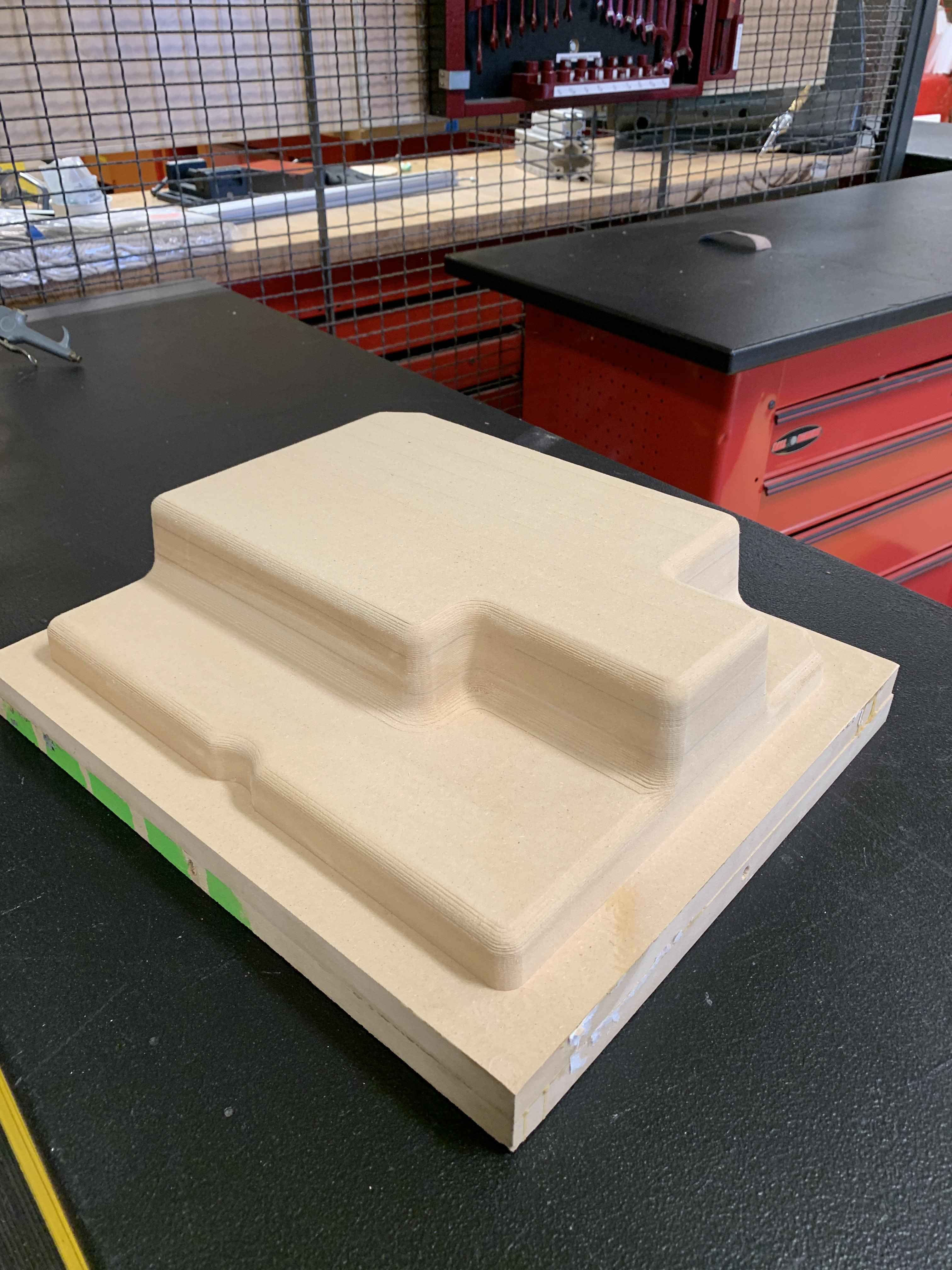
MDF mold for carbon fiber layup
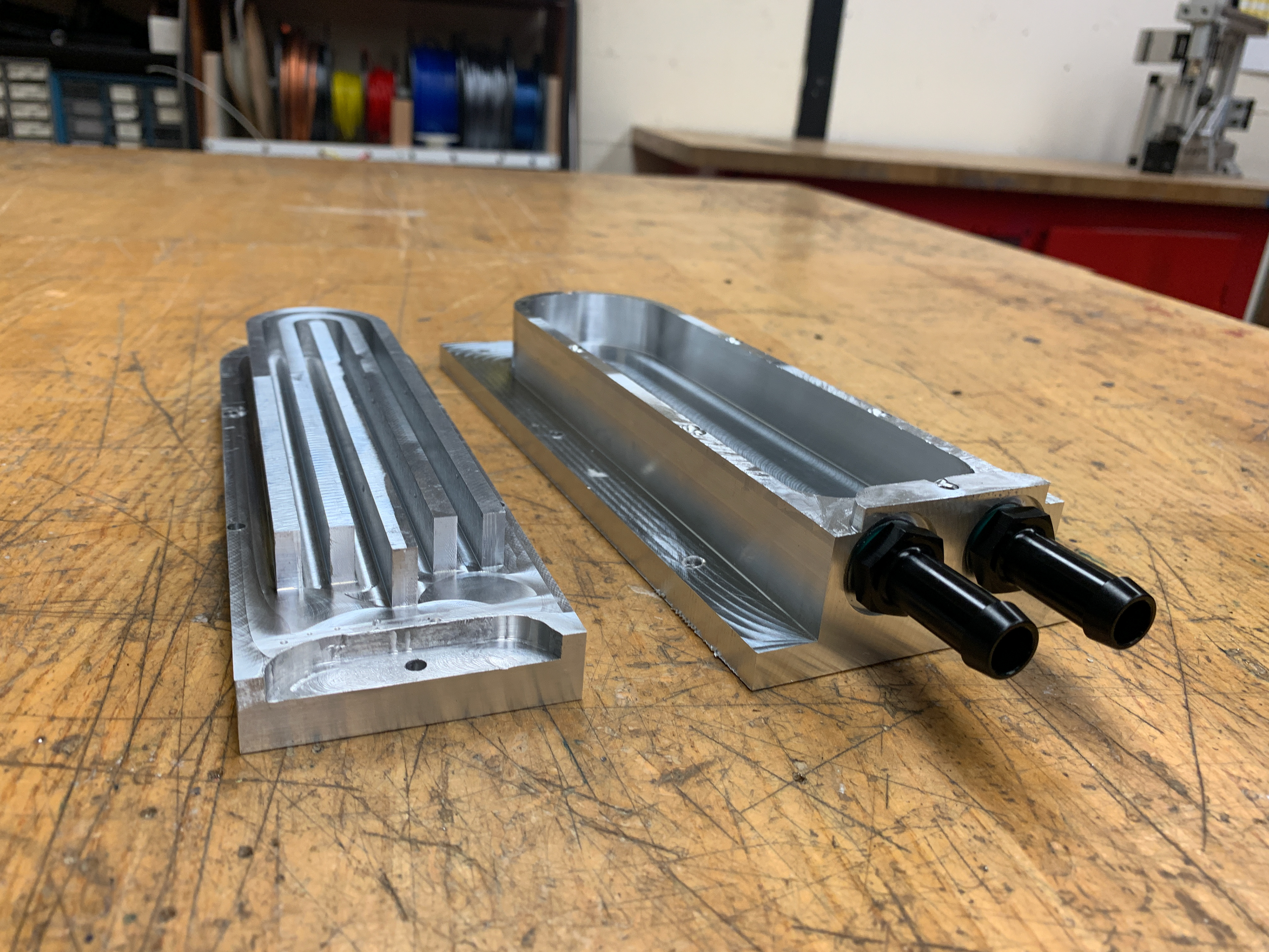
Both halves of CNC-machined waterblock
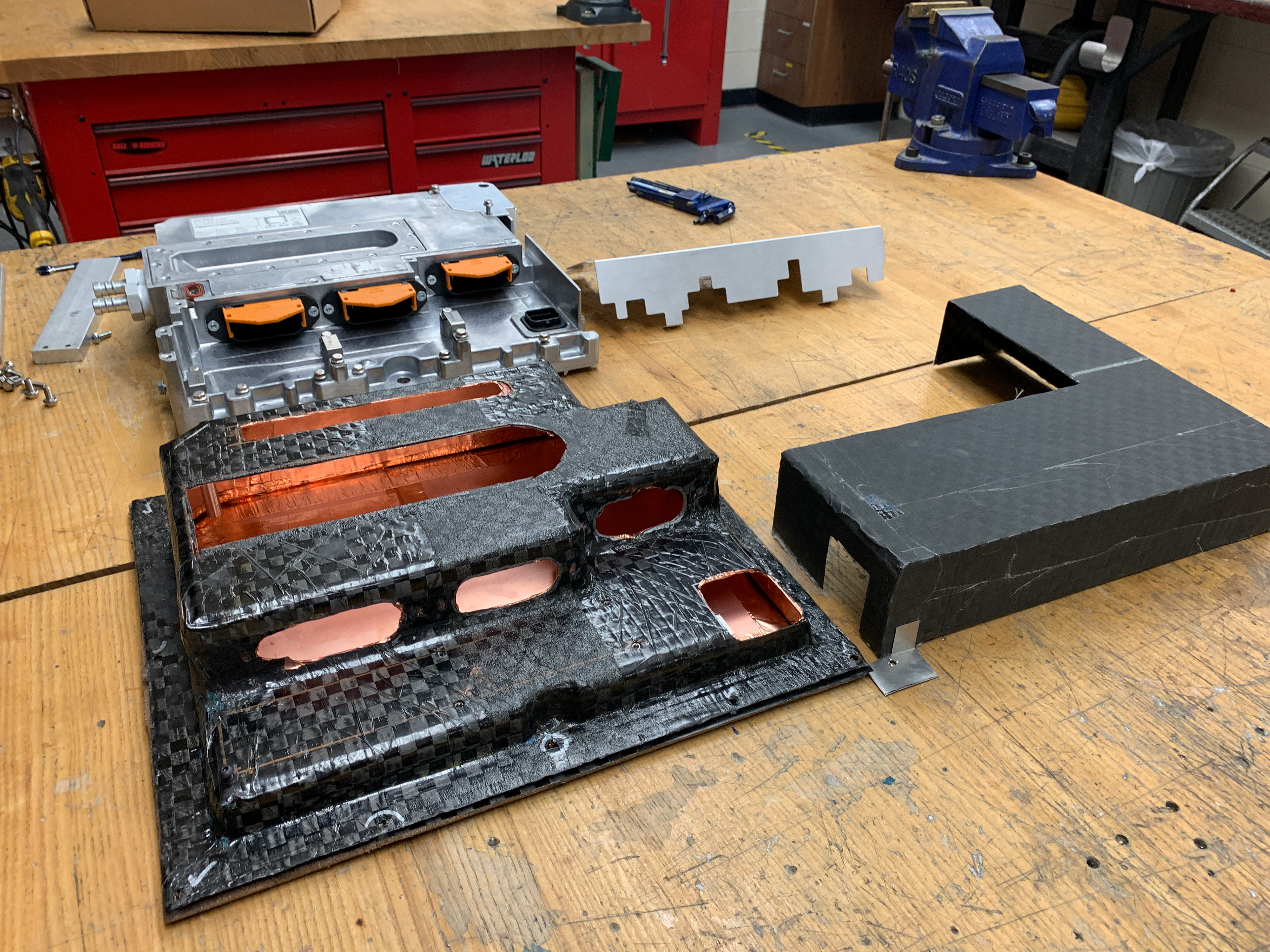
New housing (front) and old housing (back)
Autowipe 2000 (Fall 2020)
I love a good class project that requires a video deliverable (in case the Serenity Meow didn't make that clear) so when I heard my Arudino programming class (ME 451 at OSU) had a video requirement for the term project, I jumped right in. The focus of the course was sensor and microcontroller fundamentals with an emphasis on the connection between real world phenomena and how we measure them. Living in the lovely pacific northwest, I was in no shortage of inspiration for my final project concept: a pair of goggles with windshield wipers that turn on when it's raining. Who am I kidding, I had a blast creating this project and documenting the process. I learned a lot about Arduinos and sensors in the process, as well as a lot about housing/fixture design for the electronics.
Remote-controlled Door opener (Spring 2020)
The spring of 2020 was interesting to say the least. With the onset of the COVID-19 pandemic hitting education institutions worldwide, it was a new experience to say the least. During my spring term at Oregon State in 2020 I was lucky enough to take a course called Design for Manufacturing, which was luckily taught by Dr. DuPont. As the title implies, this course focused on a variety of different manufacturing methods, materials, and strategies used in industries around the globe. While learning the theory of material selection, design, manufacturing, and testing, I was tasked with creating my own functional prototype that could solve a problem I found around the house. I lived with 4 cats in the house at the time, and they were always scratching at doors to get in and out of rooms. To solve this problem, I decided I would be designing and creating a remote-controlled door opener (later called the Serenity Meow.
After some rough concept generation and market research, I had settled on a concept that looked like it would fit the bill. Part of my task for the class was to utilize a manufacturing method I was new to, and I chose to utilize vacuum forming for the cover of the electronics. I used an Arduino UNO microcontroller to receive IR inputs from a remote and transmit them to a stepper motor that was connected to a rubber wheel. All of the components were to be held in place on a custom 3D-printed mounting board made of PLA plastic. I learned a lot about woodworking and plastic handling while creating my own vacuum forming setup, designing all of my parts in CAD, and printing them on my own printer. There were some frustrating moments (broken stepper motors, 3D printer breakdowns right before deadlines) but the payoff was well worth the effort.
As a part of the assignment, I also created a 3-minute YouTube video documenting the highlights of the creation process in an easy-to-digest and entertaining way. Creating videos has been one of my passions since I was old enough to hold a camera, so I loved getting to create an educational video for this class and entertain my classmates as well as teach them a thing or two where I could.
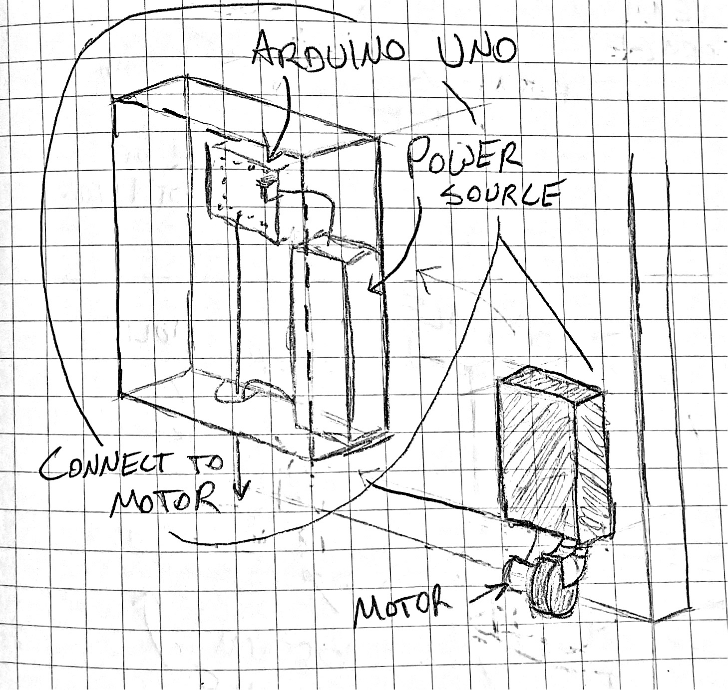
Initial sketch for door-opener
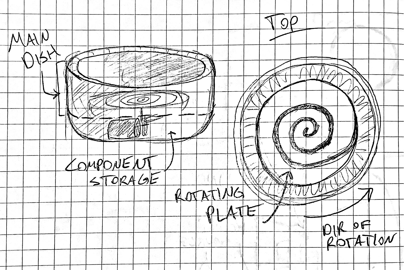
Early concept sketch for a self-mixing food dish
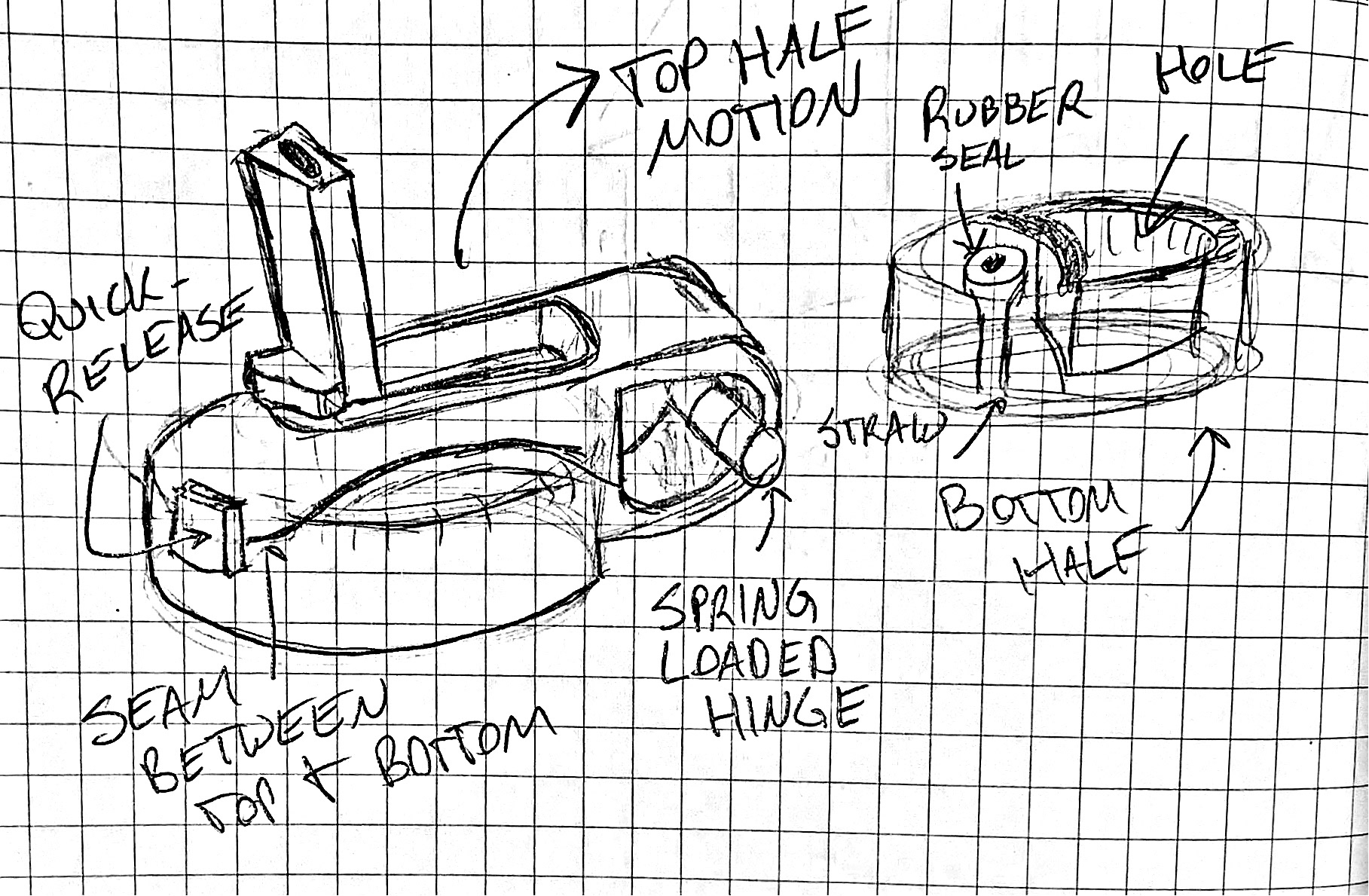
Early concept for a flip-up water bottle straw lid

Mockup for mounting board
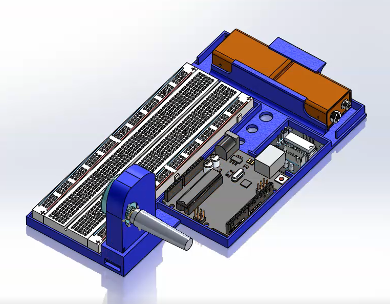
Final CAD model
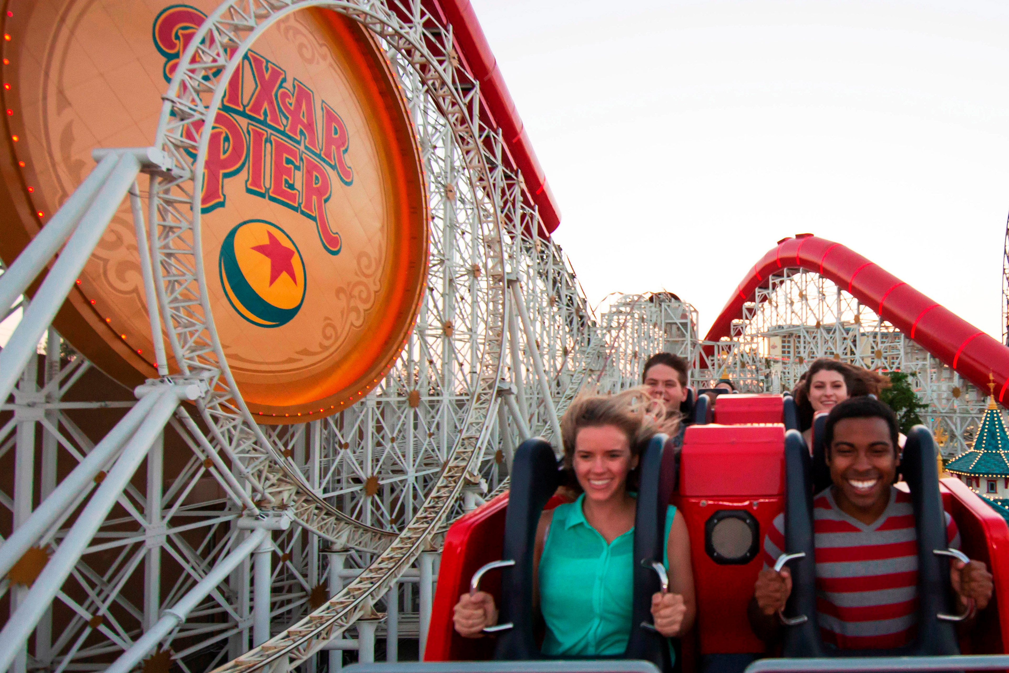
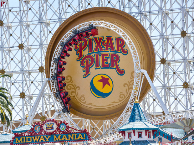
Disney California Adventure's Incredicoaster
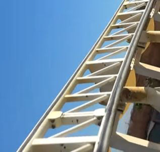
Single vertical loop of Incredicoaster showing triangular track style
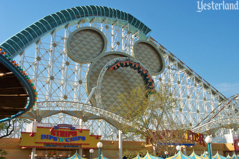
Before being rethemed to Incredicoaster in 2018, this coaster was called California Screamin'
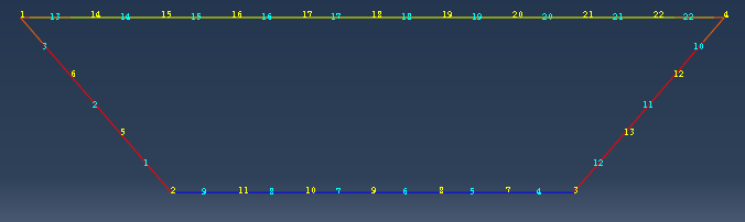
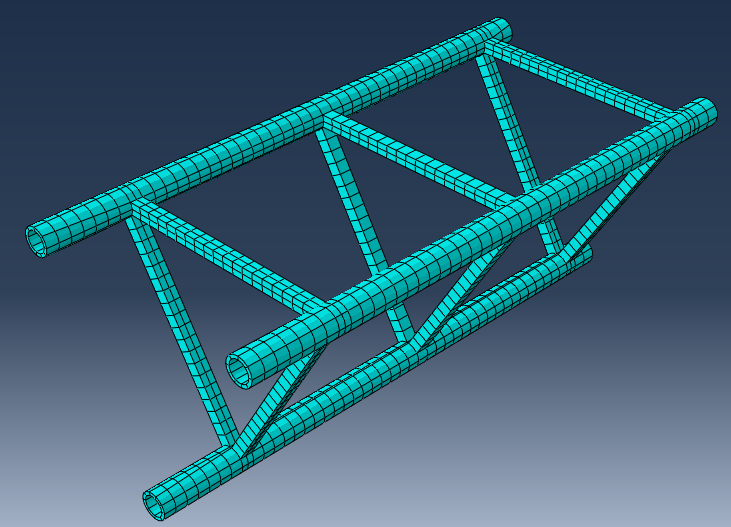
One of the two track styles being analyzed, referred to as Flat Right Cross
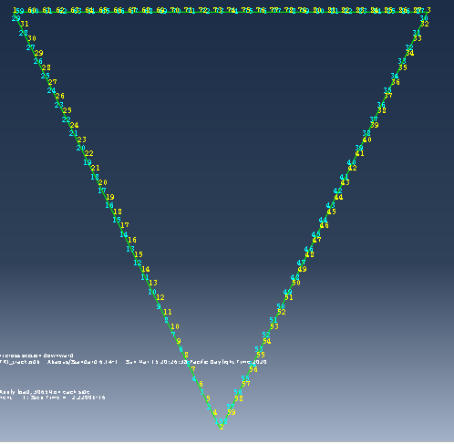
Triangular style being meshed in 2D
Support beam for flat right cross style meshed in 2D
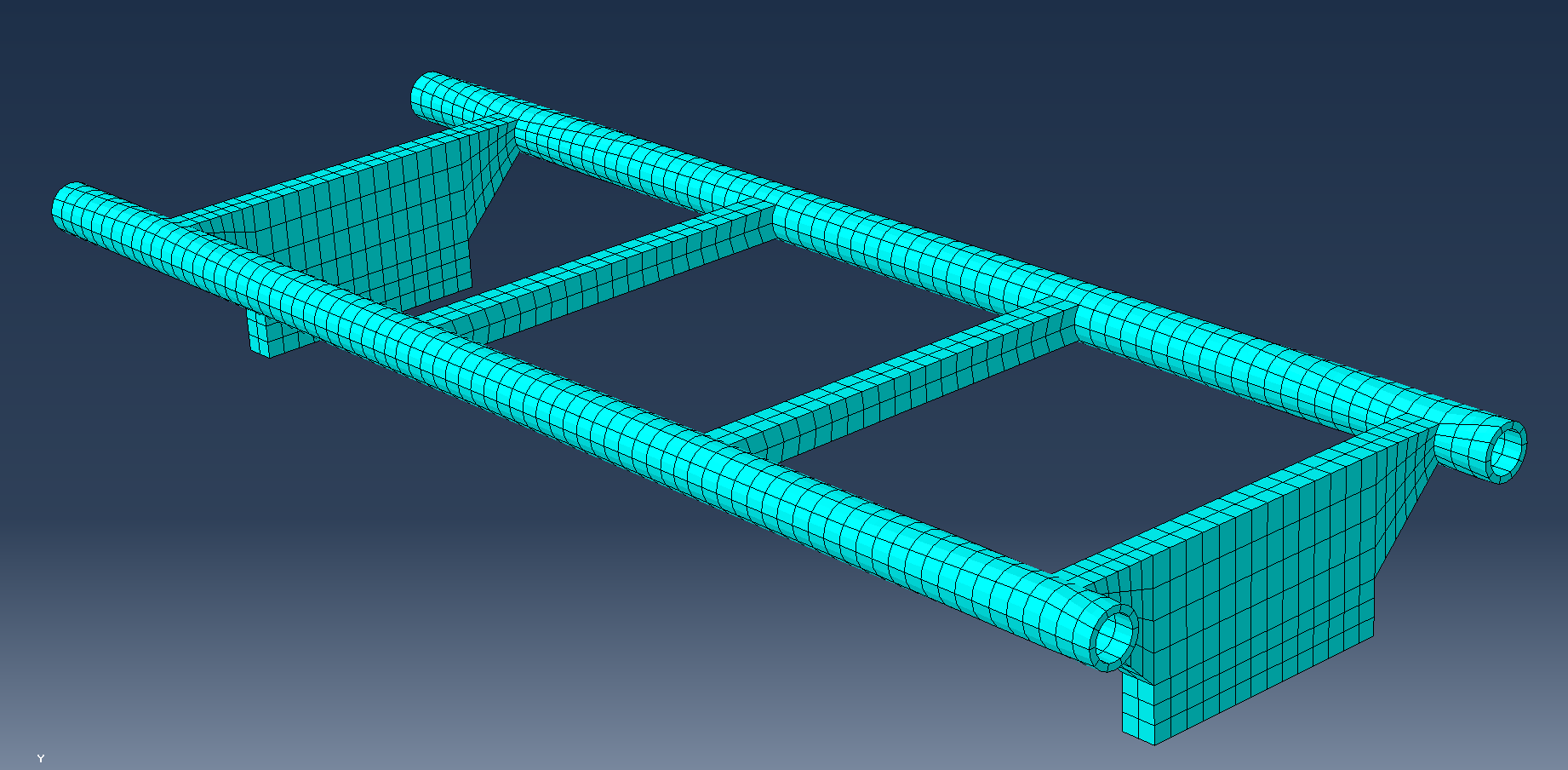
Finished mesh for Flat Right Cross style track
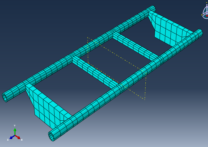
Broader mesh for Flat Right Cross (sans cross)
Finished mesh for triangular style (sans cross beams)
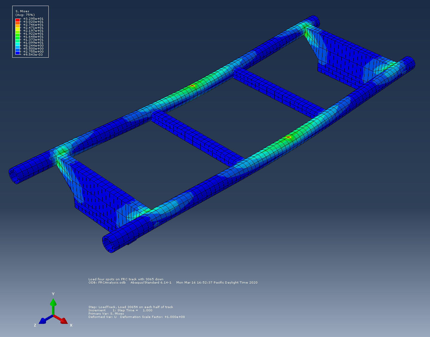
Flat Right Cross under central bilateral loading
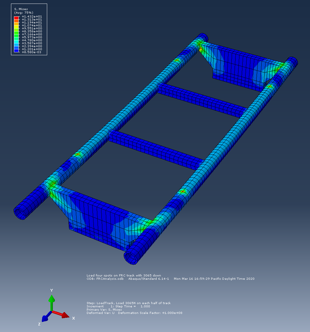
Flat Right Cross under loading at four corners
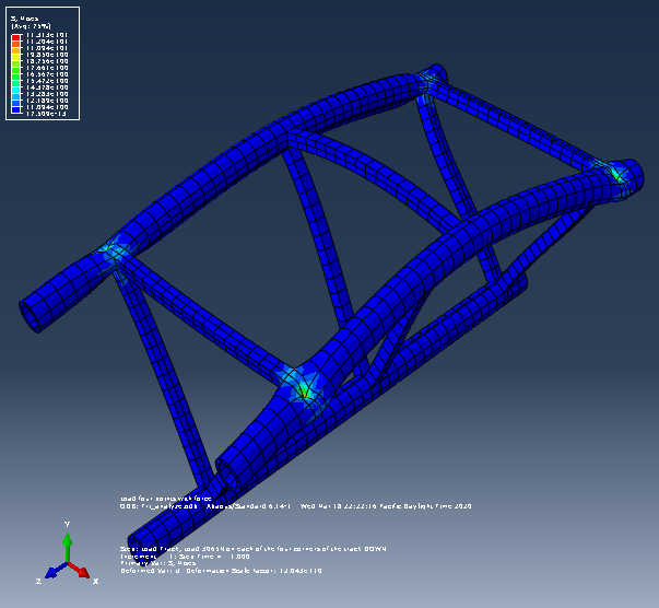
Exaggerated loading of triangular style at four corners
Roller Coaster Track Finite element analysis (Winter 2020)
Nearing the end of my fourth year (of five) at Oregon State University, I took an elective course on the basics of finite element analysis (FEA) under the instruction of Dr. Brian Bay. The goal of the 10-week course was to introduce the basic concepts of finite element analysis using Abaqus as the software of choice. Students were allowed to select a mechanical component of their choice and to set up a loading scenario that would allow them to answer a question about its functionality.
I am a huge fan of Disney theme parks, and aspire to work as a theme park designer in some capacity someday. I managed to find a way to fulfill the requirements of this project and have fun doing it by analyzing a cross section of roller coaster track. I've been a big fan of thrill rides my whole life, but I noticed that different roller coaster manufacturers use different styles of track for their roller coasters. Using this excellent class as the perfect reason to find out, I chose The Incredicoaster in Disney's California Adventure theme park in Anaheim, California as my subject.
I had a blast getting to dive into something I'm so passionate about. I reached out to manufacturers and OSU faculty for information and advice on how to proceed. During this project, I worked with CAD modeling, approximate analysis techniques, mesh analysis, and finally FEA simulation. My objective was to determine the benefits of using triangular-style track versus "flat" tracks in different loading scenarios. I ultimately estimated the rough dimensions of a single cross-section of track, as well the forces involved in the analysis, and learned a lot about how roller coaster tracks function structurally, acoustically, and aesthetically in some cases. All of the information I gathered as well as my analyses were compiled into a technical project report at the end of the course.
Remote-controlled Blimp (Fall 2018)
As a junior at Oregon State University, I took a course called ME 382: Introduction to Design, taught by Dr. Bryony DuPont. The goal of the course was to introduce common design practices like finding a need, designing and prototyping a solution, testing, manufacturing, and implementation. To practice these skills, the class was split into teams of four and tasked with designing a remote-controlled blimp that can pick up and release balloons into a receptacle in a competition at the end of the quarter. Easy, right?
Actually not so easy, but definitely doable with such a good team. We quickly found where each of our individual strengths could best help the team progress and hit the ground running. We were given a set of design constraints and came up with our own ideas, then combined the best parts of each concept into our final design. We settled on a final design using common design analysis tools like a house of quality, go/no-go, and decision matrices.
For our balloon-collecting mechanism we settled on a lightweight balsa frame with two actuated panels that could open and close. Over the course of a few weeks we cut and sealed our Mylar bladder, cut and assembled our balsa frame, 3D-printed motor mounts, and prepped our operator for the competition. At the end of the 10-week quarter we managed to place 4th out of 31 teams, only 7 of which were even able to capture any balloons. Our project was documented in detail in a 32-page technical report, including concept images, bill of materials, performance analysis, and improvements.

Tubular capture concept

Torus Blimp Concept

tri-pod collection concept

Frame, electronics, and power unit

Cutting the shape of the bladder from Mylar sheet

Using an iron to seal the Mylar sheets

Testing the buoyancy of the blimp

Finished blimp with trap-door deployed

Blimp collecting balloons in competition
